4 bit adder. Took me a few evenings this week to put together. Im quite happy that it worked first try without any bugs. Constructive criticism is encouraged.
Looks great! It looks like you might have watched my video :)
Not knowing the schematic, is there a specific reason you have those yellow traces broken out to the left? Looks like you could have done them single wires.
De obfuscation and pin hole crowding. I was struggling to fit the wires and see my pin holes so I moved the 4 wires that would have been on top of eachother over to make room for the rest of the wiring.
Ah. My only suggestion then would be to reduce the likelihood of errors by just combining each pair of black wires with its yellow wire, so it’s one continuous wire. It could still follow the same route and keep your main section less crowded, but there’d be fewer connections to worry about. And you could hold them there with little jumpers like you did in the top right section.
Thank you.
Nice wiring. Great job!
Thanks. Keeping the wireing neat allowed me to walk away and pick it up again without losing what i was doing. It also helped me get it so the first time I powered the circuit it worked as intended.
Absolutely. I always found it satisfying to route wires and avoid the rat’s nest.
Adders are the foundation of electronics. Are you going to continue on this project or start a new one? 7-segment display?
Going to ponder my next project. I want to make a counting circuit. Basically just a bank of adders on a clock signal putting the output into memory then feeing that number back into the bank and add 1.

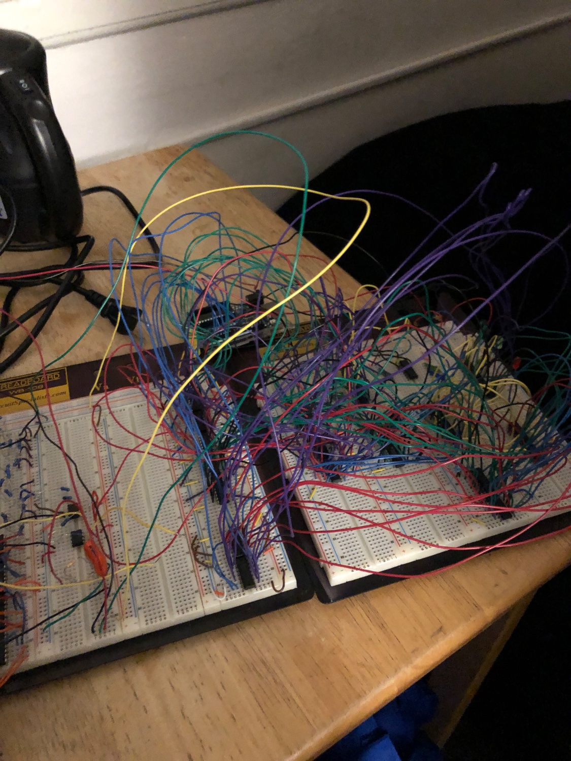
Here’s my attempt! (Actually this is a rudimentary 8-bit processor, minus a few pieces).
C’thulhu would be proud.
Looks great!
If your are looking for pur aesthetics, I would recommend trimming the resistors/leds, and bending their leads before putting them on.
If you’d like some inspiration this guy has some of the best looking hand crafted electronics I’ve ever seen.
I dont want to trim the led or transistor leads i enjoy the aesthetic of them riding proud on the board.
That’s some Ben Eater looking bent wire. Nice work!

