hello comrades! It’s been a minute! I’m back with my first tech update since upending my entire life and getting re-settled! Let’s talk 
What I’ve been up to
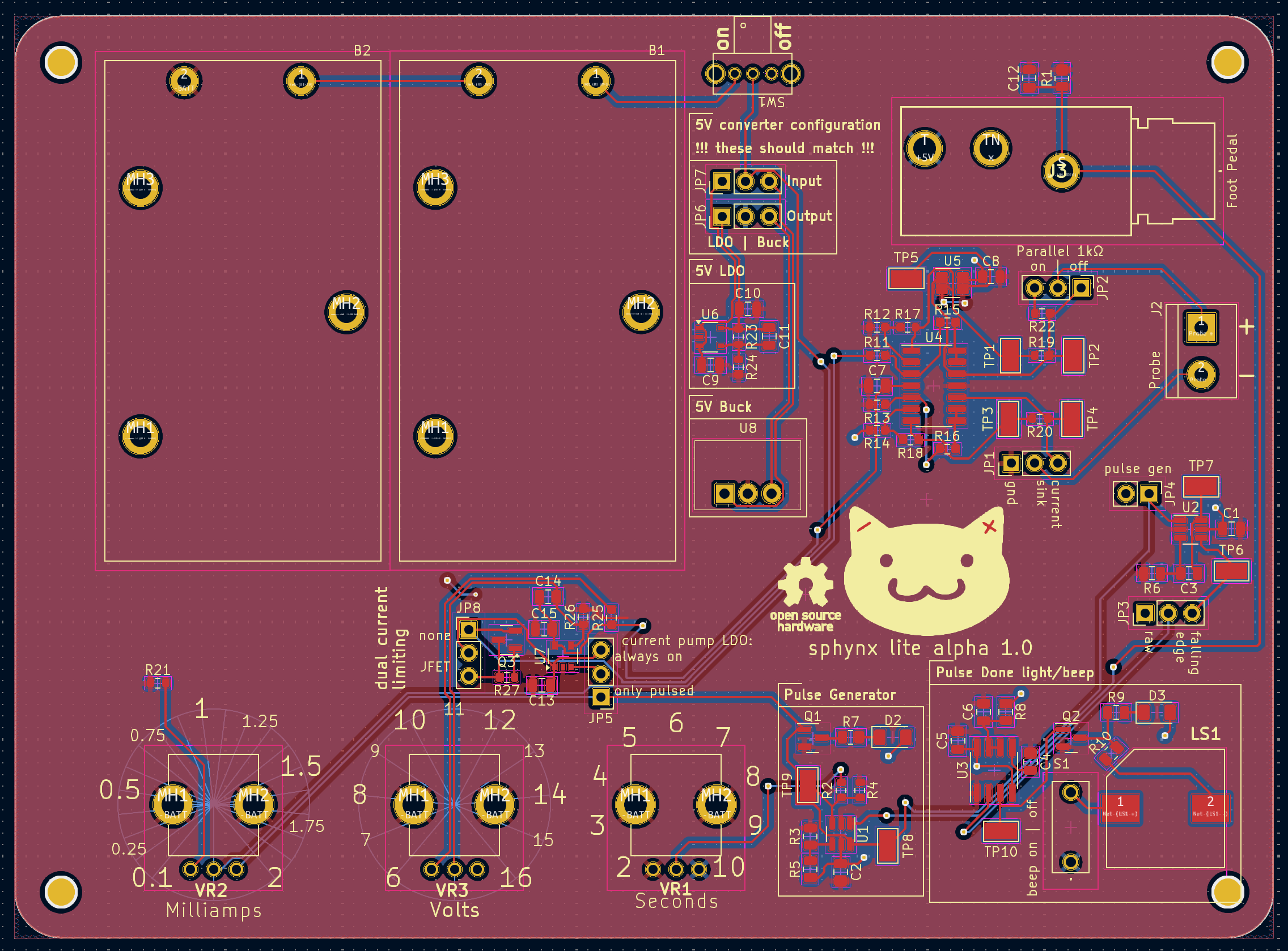
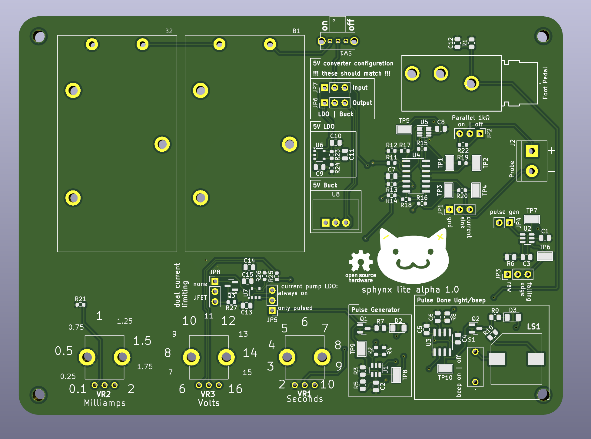
See for yourself, pictured is the first alpha of the Sphynx Lite. Schematics are on git, go check it out (and if you want to set up KiCAD to view or edit but aren’t quite sure how, say so in the comments and me or someone else will help you out!)
Issuing guidance on the usage of these things is complicated. I’m always going to be a little apprehensive recommending that people use this, because I’m a very cautious person. For now, I think my official guidance is:
- you should understand the circuit
- you should have basic debugging equipment
- you should have the time to work with it extensively
- if you meet all of the above, I provide this with no warranty and no guarantee, knowing you full well have ideas as to what you might want to use it for
- If you have a decent working knowledge of electrical engineering and want a walkthrough, I might make a Matrix so I can actually communicate with people looking to get it going??
As it gets more mature and I revise and revise until I drop the alpha, I’ll trust it more.
This was a push across the finish line. I optimized for getting something testable done with the correct topology, layout is a little dicey (cut off silk screen in the bottom right  ) and subject to change, I just needed something to test on. I was gone for over two weeks from my last post here, mainly because it was just a lot of work with nothing intermediate to report. But now it’s here! This has all the working parts of the last boards merged into one, with the new additions of:
- power conditioning
- 9V battery holders
- additional safety measures, like the redundant current limiting JFET
- configuration jumpers! and test points!! !!!
Oh, and I whipped up a cute lil logo. :3
Schematics
schematics in here


Board Layout
board layout in here


Board Renders
board renders in here


Next up
I have a lot of really good work from y’all that I need to capture and incorporate. Particularly, my immediate plans while this board is fabricated and shipped are to:
- Incorporate @[email protected]’s patchset porting the site to Jekyll - really thank you so much for this, I’ve been extremely focused on the board, and now that I have a minute, I can get the site going so I can use it to show off, post guide, aggregate educational resources, etc. This is going to be absolutely necessary for the project to have the reach and accessiblilty I’m hoping it gets. Thank you.

- Build a probe per @[email protected]’s work into coming up with a probe holder. I have a handful of the Yasutomo’s to experiment with. This is going to be a game changer, currently I’m doing self-work with an alligator clip and it’s extremely irritating. An ergonomic and reproducible probe with an extremely cheap parts list is critical for the project to function. Thank you.

- More of you provided meaningful help than just these two, these are the two who’s work I’m directly interacting with this minute. Thank you to everyone who has stopped by and made suggestions, I’ve read them all.

The next post will be me building this out and reporting on how well (or whether) it works, and documenting changes for the Lite Alpha 2.
I also badly need to make a BOM. With some effort, anyone who’s built a board together can buy all the parts for this and make one, but it’d be a thousand times easier if I just made a single cart that you can buy that includes every single component. If you want to make an alpha board for fun or debugging, maybe hold off until I have that out.
Any ways to help?
Honestly, those of you who are following this pretty closely have a good read on what’s going on, what’s needed, and what’s upcoming - keep being interested! If anyone wants to make one, I do recommend waiting until I release a BOM, but very soon we miiight be at the point where other people besides me get one of these in their hands.
I could also use some polish on the logo. It’s fine, but it could be cuter, and the lines are a bit funky. I’m going to put SVGs on git soon and if anyone feels like cleaning them up, rearrange the kitty cat face so it’s cuter, fixing my wonky paths, let me know!
Also, and I simply cannot stress this enough - when I’ve been exhausted, when I’ve been deep in executive dysfunction, when I’ve been not feeling up for it, I’ve read through all your encouragement and support throughout the duration of this project and it’s helped me to keep pushing. I would unquestionably not be this far without y’all. Thank you all so much. 
As always, stop by, hang out, say hi, ask questions, tell me what you’ve been up to, design review me, however you’d like to be involved is good by me! I’m thinking I want to make the expected cadence of posts once every two weeks, just because I’m busy and I don’t want to cause alarm when I miss a week. I can always surprise y’all with more frequent posts too.
P.S. - I have no hair regrowth in test areas. 


*bonk* you already know what I’m gonna say, this board could be a quarter of the size if you packed it and put components on both sides. Even if you stay single-sided components for assembly, I totally think you could do 100x100mm if you removed the 9V holders and used pigtail-style 9V holders, or (if that causes trouble for assembly) even barrel jacks and some off-the-shelf holders for users.
I like submodules (hierarchical sheets? I’m still on kicad 6 lol) for schematic organization but I guess they make it harder to make your board dense since you end up trying to pack rectangles together.
But I looked at the JLCPCB prices and squishing it down is probably only necessary for your pride. If you start distributing these in numbers high enough for the cost to justify the extra trouble, somebody will rip off the design and start selling it on Amazon and it won’t be your problem anymore.
I will say that committing to an enclosure helps other stuff a bit. Instead of needing the big board space for the batteries, you can just have a pigtail holder and a place in the case where the batteries sit. Depending on how you did it, you’d also have more freedom in (a) less silkscreen space around the pots (b) components between the pots without users brushing them with their fingers. FreeCAD actually has a plugin to import KiCAD models from the 3d view (and then export to some other tool’s format if FreeCad isn’t your jam) so you could make a simple 3d printed case or something. Or (deja vu, sorry if I’ve already suggested this) you could put it into a guitar pedal case. Seems like a natural fit with the 1/4" jack. Once the project is solidified a bit more and I’m less busy I’m likely to order a board, try it out, and possibly design a case.